How I automatically water my plants - with Home Assistant and an Arduino
Published: 2023-01-08
My girlfriend and I had a 16 day vacation coming up, and I stood in front of a problem: what do I do with the plants on our balcony? You could either bother someone with the task of watering them at least once daily - or you could automate it. That second thought spoke much more to my inner nerd, and it seemed like a good project to take on. Of course, I could have gone the easy route and just bought some pre-built system, but they lacked a few things that were essential to me:
- Integration with Home Assistant
- Vendor-agnostic, meaning I could repair it myself
- Not connected to any third-party cloud service - I think the long list of disasters that we have had in this regard make this pretty understandable
- Solar-powered
So now, I started into the research part of the project, trying to understand what would be needed to actually fulfil these requirements.
Explanation of idea / Goals
After reading quite a few articles and posts on the internet, I realised one thing very quickly: lots of people have had the same idea, and it was not going to be easy. I will not take you on the journey of everything I read through, but I had to credit a few articles and sites that helped bring me on the right track. The most useful one surprisingly came from a fellow countryman.
Finally, I came up with the following component list and schematic. Feel free to use it and change it for your own needs.
Component list
- Irrigation Set. I used a pretty cheap Drip Irrigation set from Amazon
- Magnet Valve
- Grid Board to solder components to. I also used one out of a set off of Amazon
- TP4056 Battery Charger Module. Be careful to choose the one that can charge the battery and also power whatever component after it. There are ones that only charge the battery, that is not what you are looking for. Here is a link to what I used.
- A LM2596 DC/DC Buck Converter. Again, I used something generic off of Amazon.
- A Battery Holder Case
- An ESP8266/Arduino with integrated Wi-Fi. I used a Wemos D1 Mini NodeMCU
- A Channel Relay with Optocoupler
- A 3,3V LDO
- A 100μF Capacitator
- A waterproof case
- 16V solar panel
- 12V PSU for testing
- Waterproof Enclosure
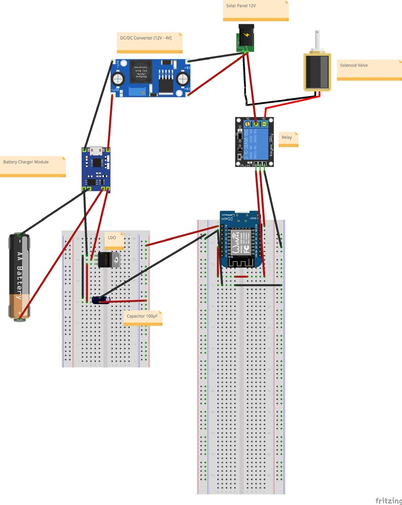
Schematic
Execution of the project
First test with Breadboard
After I drew the schematic in theory and had assembled all the parts I thought I needed, I first tried to set up a working prototype of the ESP opening and closing the magnetic valve. I used a breadboard and some cables I had lying around from an Arduino starter kit. I also used a 12V power supply to make the testing easier. The end result was what you are seeing in the picture.
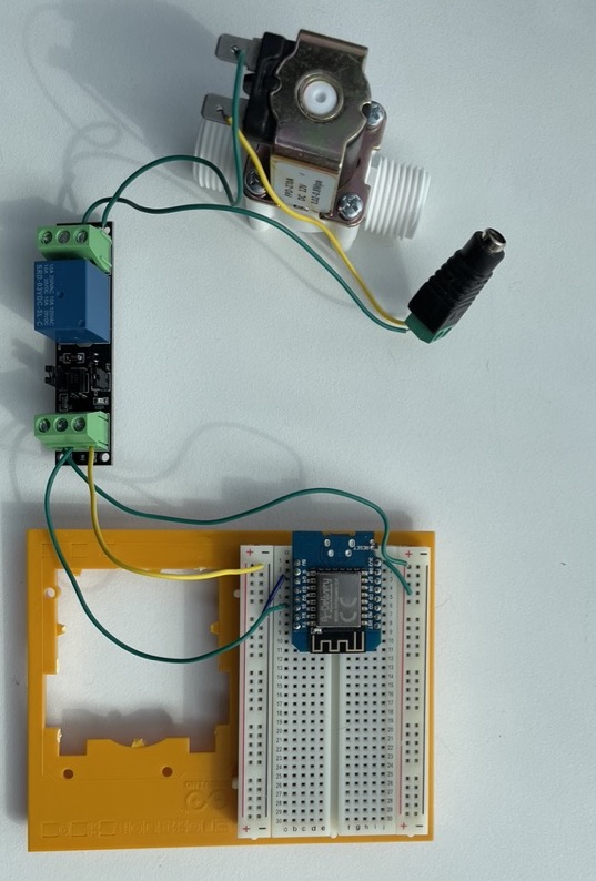
I used the Arduino Blink starter program to test it out. All it does is send current out of a digital pin in a set interval.
And would you believe it, it worked on the first try. The relay and thus the valve were opening up every second, as expected.
Home Assistant integration
The next logical step for me was to test out if I could integrate the Wemos D1 mini into Home Assistant. For this, I had to take two steps:
- Get the Wemos programmed in a way that it would take in MQTT commands
- Integrate it into Home Assistant so that I could send commands out
Code for the Wemos MQTT integration
As my first inspiration for what the code could possibly look like, I went with what I found on the blogpost mentioned in the intro again.
I modified some of it to get it better in line with what I wanted to do. Here is the full code I am using at the moment for the Wemos D1 mini:
[#include] <ESP8266WiFi.h>
[#include] <PubSubClient.h>

// WIFI
const char _wifi_ssid = "YOUR_SSID";
const char_ wifi_password = "YOUR_PW";

// pins
int relayInput = 5;

// MQTT
const char _mqtt_server = "YOUR MQTT SERVER_IP";
const int mqtt_port = 1883;
const char_ topic = "esp8266/pin"; //replace this with whatever you want the topic to be
const char _availability_topic = "esp8266/pin/available";  //same as one line above
const char_ mqtt_username = "YOUR_MQTT_USERNAME";
const char *mqtt_password = "YOUR_MQTT_PASSWORD";

int status = WL_IDLE_STATUS;

WiFiClient espClient;
PubSubClient client(espClient);

void setup() {
	Serial.begin(115200);
	pinMode(relayInput, OUTPUT);

	WiFi.begin(wifi_ssid, wifi_password);
	while (WiFi.status() != WL_CONNECTED) {
		delay(500);
		Serial.println("Connecting to WiFi...");
	}

	Serial.println("Connected to WiFi Network");

	client.setServer(mqtt_server, mqtt_port);
	client.setCallback(callback);

	while (!client.connected()) {
		char* client_id = "esp8266-client-irrigation";
		Serial.println("Connecting to mqtt server...");
		if (client.connect(client_id, mqtt_username, mqtt_password)) {
			Serial.println("Connected to mqtt server!");
		} else {
			Serial.print("failed with state");
			Serial.print(client.state());
			delay(2000);
		}
	}
	client.publish(availability_topic, "online");
	client.subscribe(topic);
}

void callback(char _topic, byte_ payload, unsigned int length) {
	pinMode(relayInput, OUTPUT);
	Serial.print("Message arrived in topic: ");
	Serial.println(topic);
	Serial.print("Message:");
	String message;
	for (int i = 0; i < length; i++) {
		message = message + (char) payload[i];
	}
	Serial.print(message);
	if (message == "on") {
		digitalWrite(relayInput, HIGH);
	}
	if (message == "off") {
		digitalWrite(relayInput, LOW);
	}
	Serial.println();
	Serial.println("-----------------");
}

void loop() {
	client.loop();
}
The code is probably not a work of art, but it does the job. What it does in detail:
- Sets up the WiFi- and MQTT-Clients
- Then tries to connect to the WiFi until it successfully does so
- Then connects to the MQTT server
- After successful connection to the MQTT server, it publishes its availability topic with a status of “online” and subscribes to the topic where it will get MQTT-commands sent to it from the server
- Finally, whenever a command arrives on the specified topic, it prints the command and acts accordingly. In our case, it turns the pin on when the command “on” is received, and turns the pin off when the command “off” is received
Integration into Home Assistant
Now that the Wemos was ready, there was still the challenge of integrating it into Home Assistant in the correct way.
I was already using MQTT components in my setup, which is why I already hat the Mosquitto Broker installed. With it, you can test mqtt integrations very easily, as described in this useful article. You can go to Settings -> Devices & Services -> Configure on the Mosquitto tile.
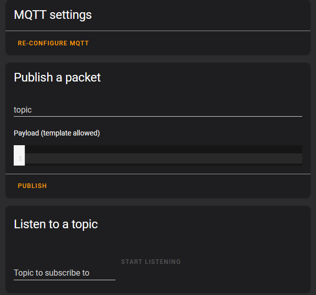
I then configured the topic to publish to as “esp8266/pin” and published the message “on”. The testing setup I used was the same breadboard setup I have described a little further up. Again, this worked on the first try. Publishing a message of “on” made the relay click and opened up the valve, publishing a message of “off” did the opposite.
Next, I had to fully integrate the Wemos D1 mini into Home Assistant as a fixed device.
I configured it as a switch, since that is basically it’s functionality. The following lines were added to the configuration.yaml file:
switch:
#Arduino Controller
- unique_id: garden_irrigation
name: "Bewässerung"
command_topic: "esp8266/pin"
payload_on: "on"
payload_off: "off"
state_on: "on"
state_off: "off"
availability_topic: "esp8266/pin/available"
availability_mode: "all"
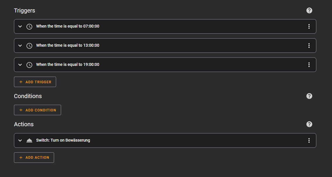
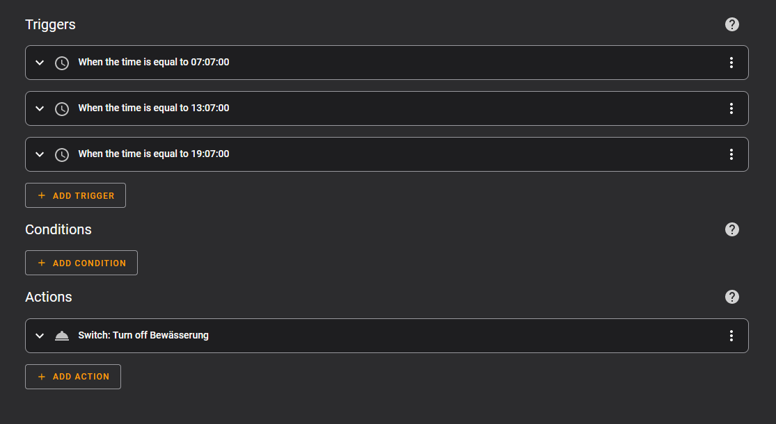
retain: trueFinally, for this to water the plants, we need some kind of automation. I opted for two pretty basic things:
- A “Water Plants” automation which turns the configured switch On at a certain time
- A “Turn Off watering” automation which turns the configured switch off at a certain time
Here is the quick overview of these two automations:
Since everything I tested up until that point worked out, I was ready to solder components together for a “final build” of the project.
Soldering of components
To be honest, I had never soldered anything together before. I bought a starter kit and just went for it. Worst case, some of the components would break, which could easily be replaced for less than a euro. A tip that I can give here: just try it, it is much less difficult than it looks. I watched a few youtube tutorials, and tried to apply the techniques as well as I could. The final result is not great to look at, far from it actually. But it works, and that is exactly what I was aiming for.
What I felt was a very good decision was to solder the pin headers on the board, so that I could change out the ESP in case it broke or breaks in the future, as you can see on the pictures.
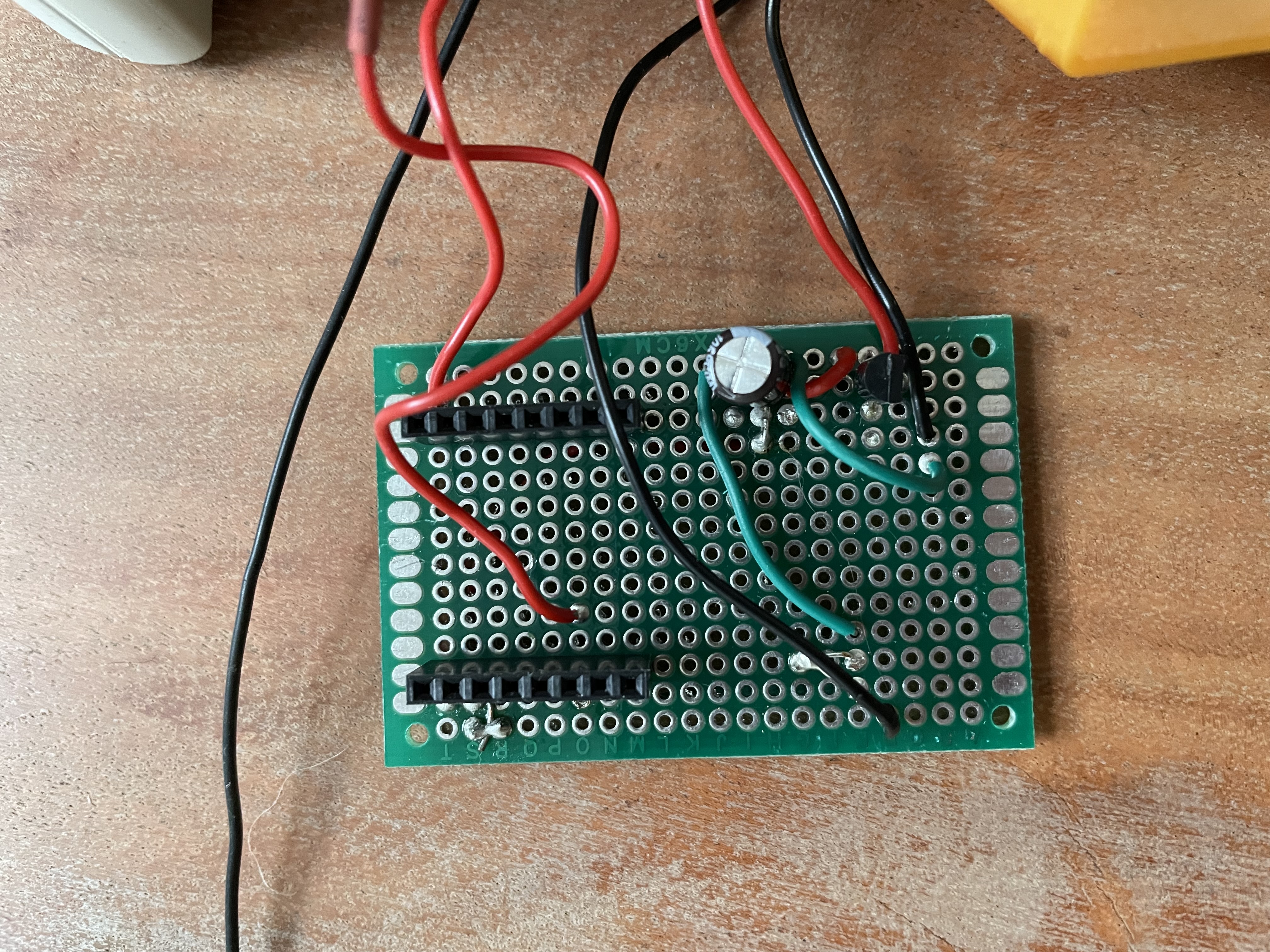
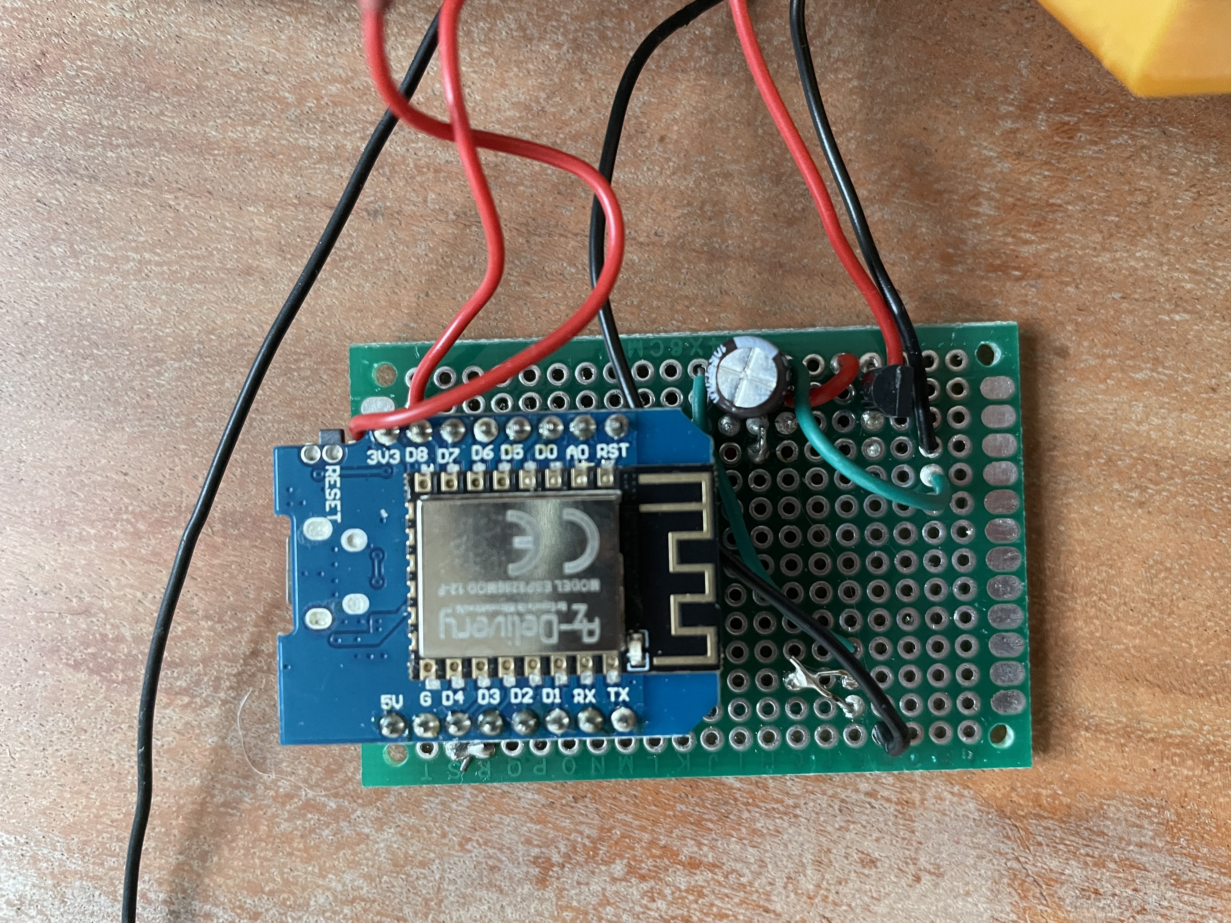
The Wemos just clips into it, which is very convenient.
The end result of the soldering is a wild mess of cables that I fit into a waterproof enclosure I bought at the hardware store.
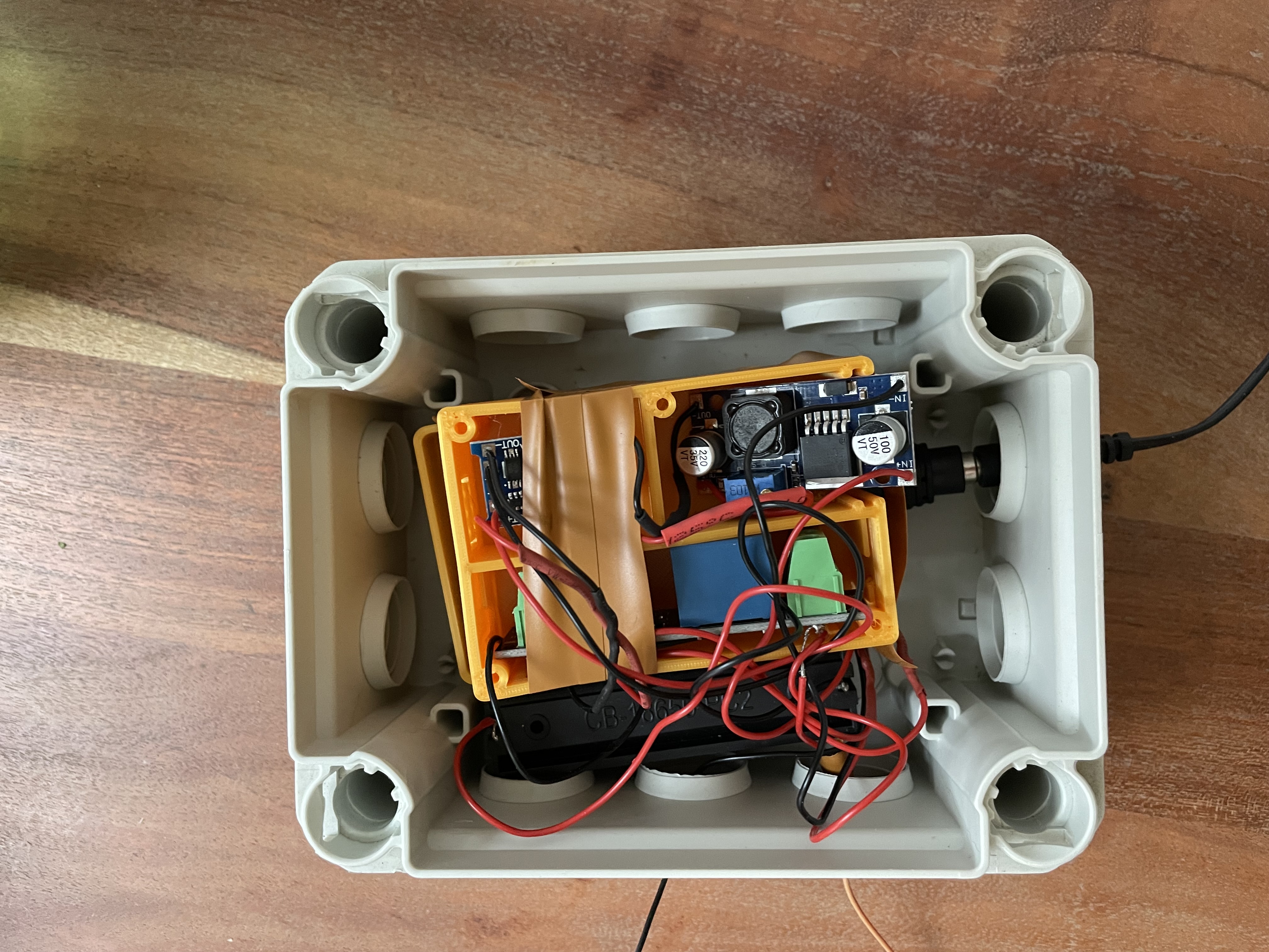
The orange enclosures were 3D printed to at least have some semblance of order in the enclosure, and to avoid possible short-circuits.
First testrun
After having all of this work out in theory with the power supply, I now needed to make it work in practice. Since the main power source was supposed to be the solar panel, I went outside and tried it out.
This is where the problems started.
Unfortunately, it seemed that the solar panel was enough to power the Arduino, but not enough to power the whole circuit when the valve should be opened.
I did not have much time left before our trip, so I needed to improvise. The solution was pretty simple: use the power supply. I just had the cable go through our balcony door and into the waterproof enclosure. That gave me the possibility to water the plants for our holidays.
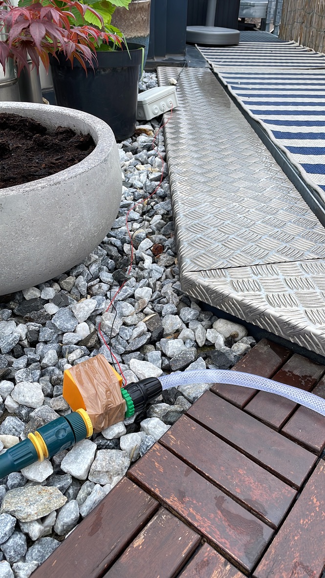
And it actually worked! I did not have to bother our neighbors and the plants were happy after our return.
Conclusion
So overall, I have learned quite a few things with this project. Electronics, soldering, ESPs, the Arduino IDE and MQTT make much more sense to me now. I have also learned that it is not that hard to make something yourself, according to your needs. It just takes a lot of research and trial and error. I have to be honest: I have not upgraded the project to solar power yet since it worked so well without it. I might do that next year. If it ever happens, I will write an Update. We’ll see what the next project will be - self-built weather stations seem quite fun…